It's coming...
posted by Pehr @ 10/29/2005 01:24:00 PM
1 comments
![]()
![]()
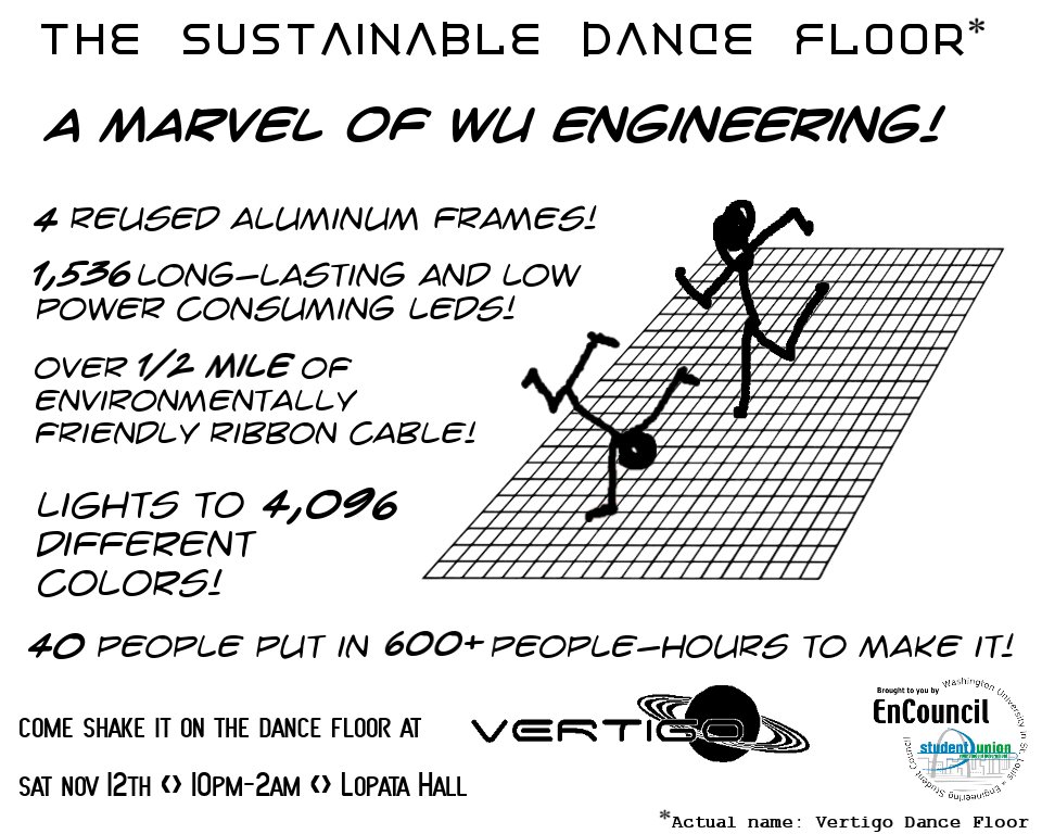
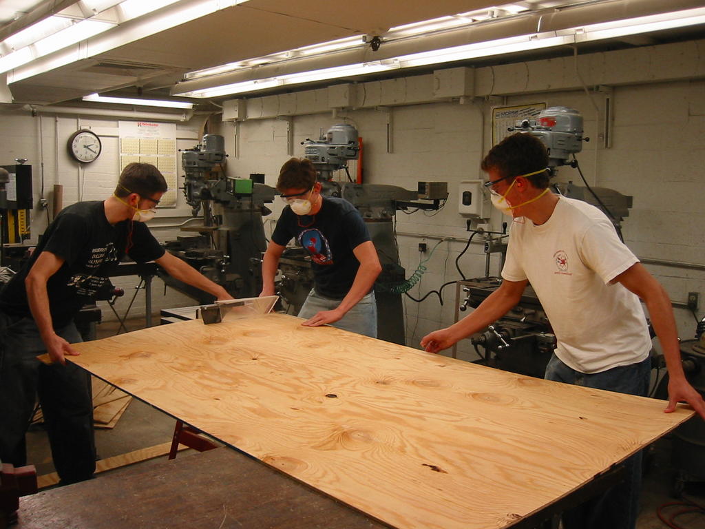
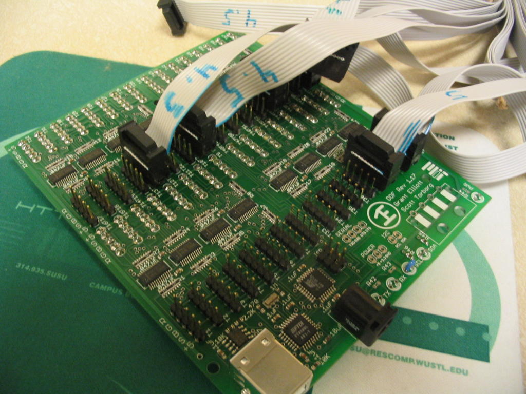
 Wash U IEEE built a large scale light-up computer-controlled dance floor for Vertigo.
Vertigo is a giant all-school dance party hosted by the Engineering Student Council and held in Lopata hall.
Vertigo 2005 Pictures!
This floor is based on one made by students at MIT last spring.

posted by Pehr @ 10/29/2005 06:10:00 AM
2 comments
![]()
![]()


posted by Pehr @ 10/29/2005 05:59:00 AM
0 comments
![]()
![]()
posted by Pehr @ 10/26/2005 02:31:00 AM
0 comments
![]()
![]()

posted by Pehr @ 10/23/2005 02:49:00 PM
2 comments
![]()
![]()
posted by Pehr @ 10/23/2005 02:28:00 AM
0 comments
![]()
![]()
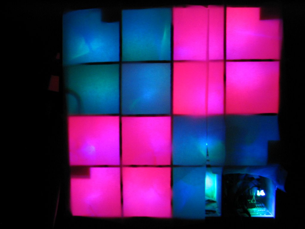
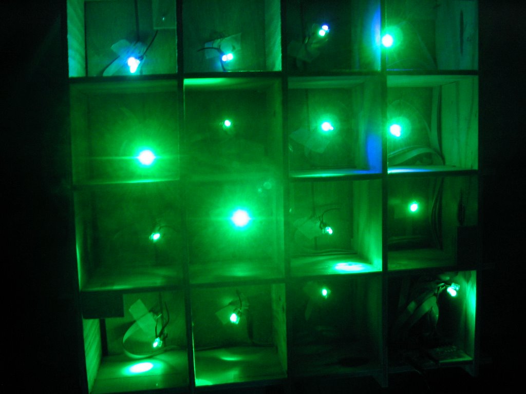
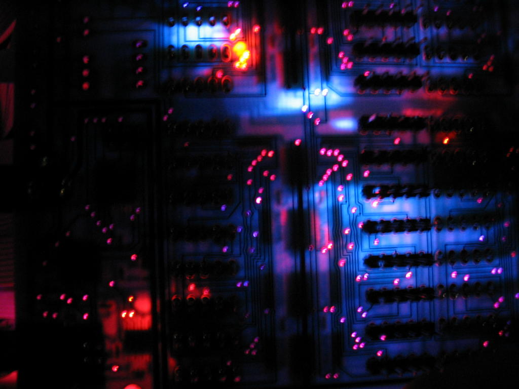
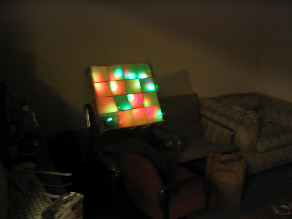
Last night, the first pixel finally turned on. We have two videos, one of two-color transitions and one of purely random colors. Check these out. Then imagine another 511 pixels next to it, lighting up the room in trippy color.
posted by Brandon @ 10/20/2005 10:31:00 AM
0 comments
![]()
![]()

posted by Pehr @ 10/20/2005 02:43:00 AM
0 comments
![]()
![]()
The Lexan for the surface of the floor has arrived! We are using 1/4" genuine GE Lexan because it is very flexible and 250 times as strong as glass. The four panels were purchased from Regal Plastic in Saint Louis.
posted by Pehr @ 10/15/2005 12:38:00 AM
0 comments
![]()
![]()
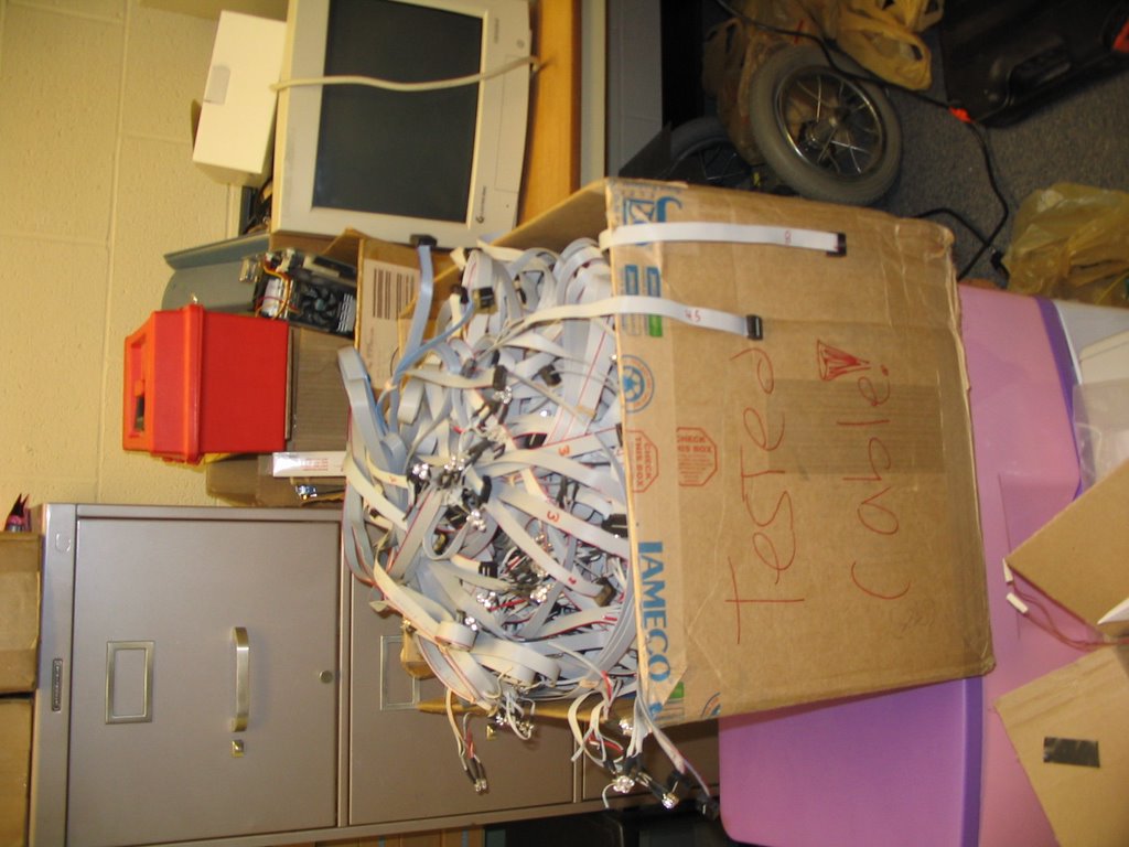
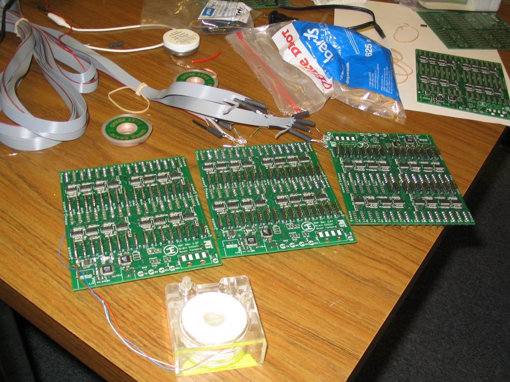
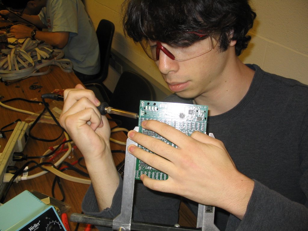
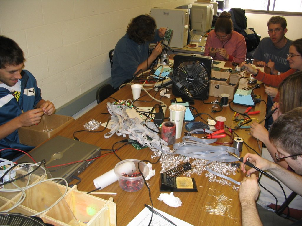
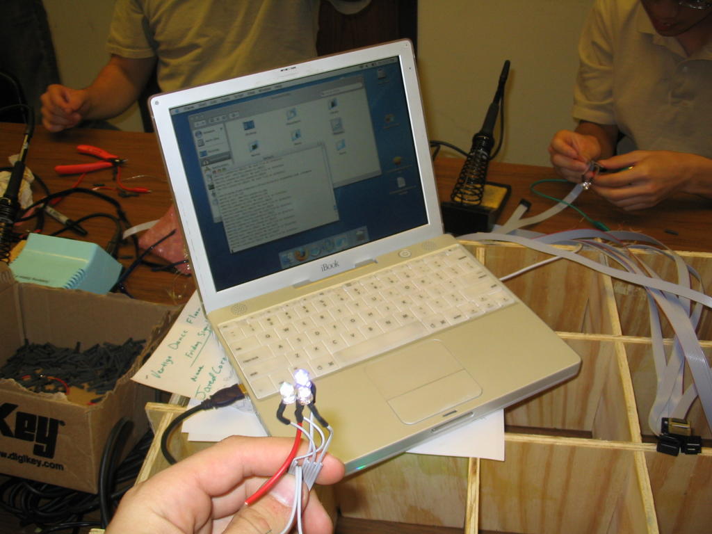
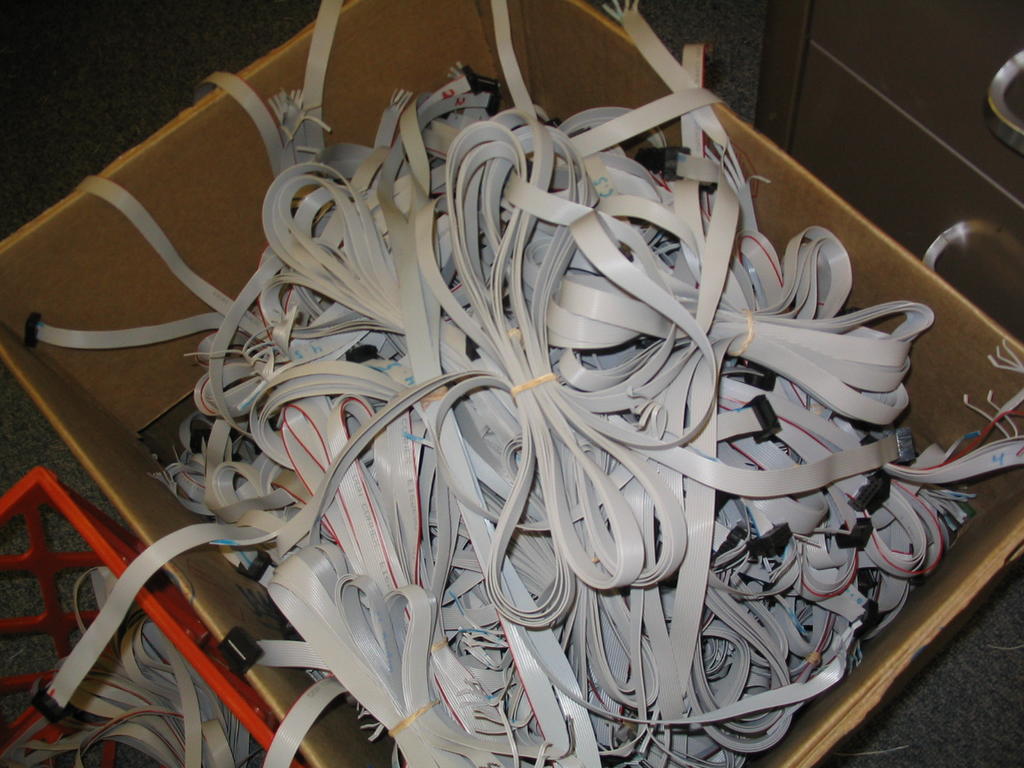
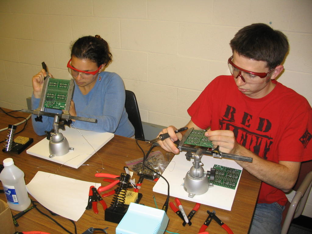
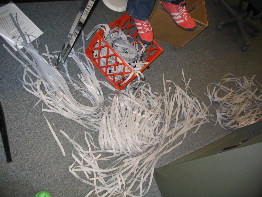
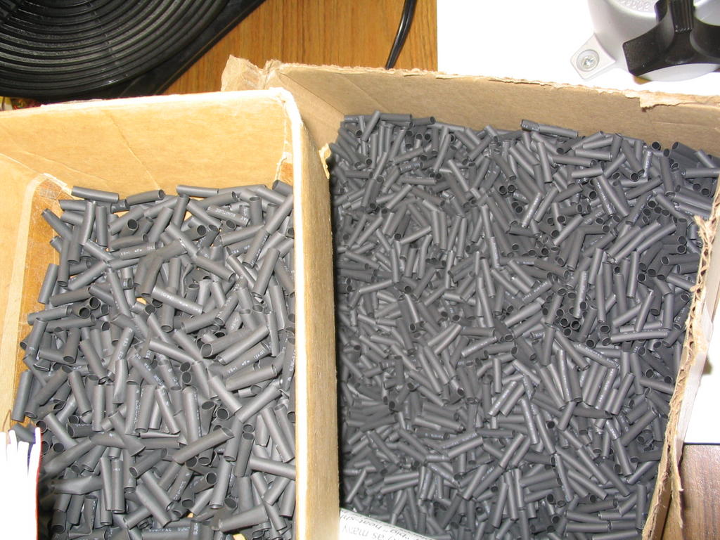
We are testing various methods to assemble the ribbon cable whips that contain the LEDs and pressure sensor for each pixel.
posted by Pehr @ 10/10/2005 12:11:00 PM
0 comments
![]()
![]()


posted by Pehr @ 10/10/2005 08:17:00 AM
0 comments
![]()
![]()