Saturday, October 29, 2005
Results! It's solder-tastic
New videos! (below)
After spending from 11:00am to 5:00am in the engineering school our crack team of solder-ers have managed many milestones. All the cable is now complete. This means it has been cut, connectored, separated, stripped, soldered-to and then heatshrunk. Out of all the cables made (~500) there were only 3 instances of faulty cables (ie, bad solder joint). This is AMAZING as we did this over the course of two weekends with 30 different people helping throughout.
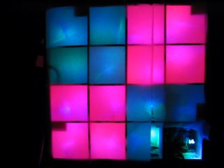
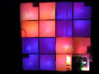
We found that by simply aiming the LED's at the back-surface of the test module and covering it with wax paper we get a nearly even coloring. We planned to do this eventually and include tinfoil and other exotic materials but were amazed when simply re-taping the LED's and having the light bounce off of the wooden backboard was nearly all we needed, as the pictures show.
Excitement for this project is building too. Last night we demonstrated our 4x4 pixel test module to the engineering student council meeting and impressed at least 30 people. This helped get people pumped up for Vertigo itself as well as our solder party we had today.
The Electrical Engineering Department gave us doughnuts on a nice platter to keep us going. They also took many pictures of us kids being constructive for publication in newsletters and viewbooks. Professor Cytron, the overseer of the software team (its a group from his class, CSE436, that is doing the software) has invited members of the media to Vertigo setup to cover the awesomeness that is this project.
We have videos of two of the test patterns included in the MIT code (not quite ready yet to write our own). These basically demonstrate the effectiveness of our current diffusing method (that is, re-aim + wax paper). We eventually may use nearly-opqaue plastic sheeting to get a more even look than wax paper but this works well for now.
Checkers
Diagonal
Pictures from Solder Party II




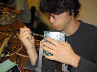

By the way, we have decided to market this dance floor to the campus community as a "Sustainable Dance Floor." Part of this has to do with a certain other sustainable party happening today that is very similar to vertigo, and the rest is that we re-used a lot of materials (including old cable and stage frames) and the 1800 feet of new ribbon cable we used is certified "environmentally friendly." Captain planet would be proud.
Wednesday, October 26, 2005
Solder Party II this friday!
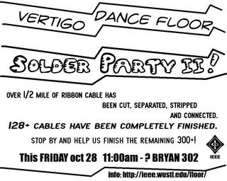
Really all that is left on the large scale is to solder LED clusters to the ribbon cable. I finished 32 cables tonight (a small amount in the scheme of things but its half a controller board's worth).
We will be doing this all day friday in Bryan 302 so make sure to stop by!
In other news, the programmers have interfaced with the test module and are beginning to test the API on the hardware. They really want some finished modules though so we are making every effort to deliver by monday.
Vertigo is in 17 days!
Sunday, October 23, 2005
More Build Party Pictures, Solder Party II: the sequel
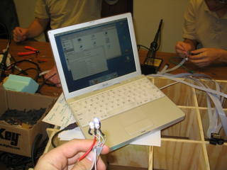
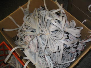
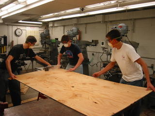
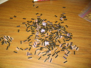
Here are more pictures of this past weekend's build party.
Solder Party II will be held all day friday starting around 11:00 am in Bryan 302. At this point it is pretty much all soldering as we have the LED clusters and a lot of heatshrink and wires cut. It takes a team of two 1-2 minutes to do a cluster (4 solder joints plus heatshrink and sensor wire).
Please stop by and lend a hand! Vertigo is 20 days away!
Also, this weekend is Halloween and Bauhaus! so we will not be hosting an official solder-party over the weekend but someone will probably be there working on it at some point.
Progress! Fall Break Solder Party Recap
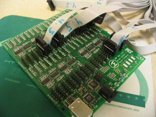
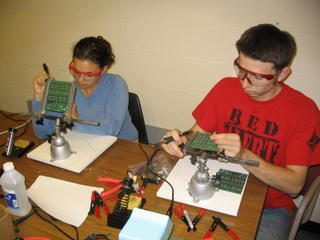

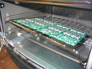
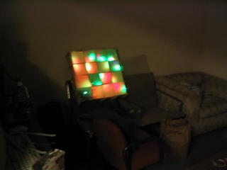
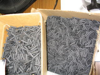
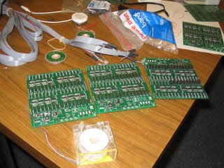
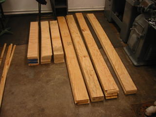
This past friday and saturday we hosted a solder party in the ESE/IEEE lounge in Bryan to get as much progress as possible done on the floor. We had the help of several generous and talented volunteers (fueled by free pizza, chicken and chinese food) we were able to consume over 3,400 feet of 10-conductor ribbon cable (more than 1/2 a mile), 1500 LED's, dozens of feet of heat-shrink, 512 snap-on cable connectors, and a syringe of solder paste.
The results:
>all the wood is cut into strips and ready to be notched (to fit them together into a grid).
>all 512 pixel-cables are cut, separated, stripped, and have their board-connector attached
>more than 100 of the pixel cables have the LED's soldered to them (ie, finished product)
>the remaining LED's have been soldered together in groups of 3.
>4 controller boards are toaster soldered and 2 of them are programmed and verified working (with headers).
>the 4x4 pixel demonstration module for the programmers needs only finishing mechanical touches.
>the floor of the lounge is a MESS.
See the results for yourself!
We have less than 3 weeks until VERTIGO so there is still a lot of work to do.
Currently it is a matter of soldering LED's and sensor wires to the ribbon cable and heatshrinking the results.
After the cables are complete they must be tested and the rest of the controller boards constructed.
Finally, the wood needs to be finished and integrated into the aluminum frames for easy transport.
Coming up soon will be Solder Party II: the sequel. This time it will be ALL soldering as the rest of the mechanicals are out of the way.
Stay tuned!
Thursday, October 20, 2005
Video of First Blinking Pixel!
Last night, the first pixel finally turned on. We have two videos, one of two-color transitions and one of purely random colors. Check these out. Then imagine another 511 pixels next to it, lighting up the room in trippy color.
The problem was due to an incorrectly inserted programming cable. When inserted backwards, the AVR programmer would still turn on, and report that everything was ok. When trying to program a chip, however, there were plenty of errors. It just so happens that the AVR 6-pin ISP connection delivers power to a programmer when inserted backwards, by drawing power from the RESET and MISO lines. With a working programmer, we could finally put the firmware on the main chips, and set them to the proper speed, 8 Mhz. Then... it worked.
Things are looking up now, with the most critical (and delayed) piece in place!
SOLDER PARTY!
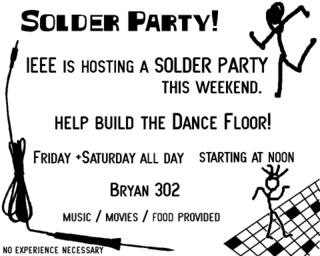
To mass produce the LED / pressure sensor whips we are hosting a solder party this weekend.
We will have teams of interested students measuring and cutting ribbon cable, stripping the ends, soldering the LED's on to it and adding the end connection. Another group will be testing each of them to verify their integrity.
We need to make 512 of these cables so it will take some time but its easy and fun!
Food and movies / music will be provided.
Details:
This Friday + Saturday starting at noon
Bryan 302 (IEEE / ESE lounge).
We will also be doing the woodcutting for the structure on friday as well.
Feel free to stop by to check on the progress and hopefully lend a hand!
Saturday, October 15, 2005
More parts
The Lexan for the surface of the floor has arrived! We are using 1/4" genuine GE Lexan because it is very flexible and 250 times as strong as glass. The four panels were purchased from Regal Plastic in Saint Louis.
The power supplies came today too. We are using 5VDC 13A bulk power supplies from Marlin P Jones & Associates (MPJA). They were cheap and compact and will be integrated into the modules.
Things are shaping up for our build weekend, starting October 21st (Fall Break), in Lopata hall.
Monday, October 10, 2005
Testing Cable, Student involvement
We are testing various methods to assemble the ribbon cable whips that contain the LEDs and pressure sensor for each pixel.
The two theories so far are to use 20 conductor ribbon cable and split it into 4 5-wire sections. Each section will service one pixel and on the board-end the individual wires could be crimped and put into headers soldered to the board.
Another option is to use sections of 10-conductor and use it with press-on ribbon cable ends (10-conductor). Only 5 individual wires would be used, which translates to one of the 2 rows of the cable connector. This results in wire waste but is faster than doing individual wires with various crimp-on connectors.
As soon as we figure out the "best" way to do this we are going to be calling out to all interested students to help us prepare these ribbon cables. There will have to be 512 of them (1 for each pixel) regardless of how they're arranged. It is time-consuming by itself but a group of people, motivated by free food) can get it done in reasonable time.
We will need people to cut the cable, strip it, make pressure sensors, solder the LEDs and sensors to one end of the cable and attach whatever connection method is used to the other end.
We will let interested people know via this site and e-mail when, and how, they can get involved.
Test Modules Built, Part orders
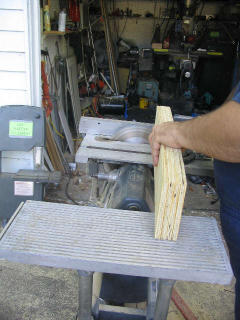
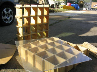
Things have been busy with the Dance Floor. Vertigo is 33 days away and the floor is starting to take shape.
We have assembled one of the 4 alluminum frames that will form the outsides of each 4x8 foot floor module. They put together with an allen wrench in about an hour, the rest will soon follow.
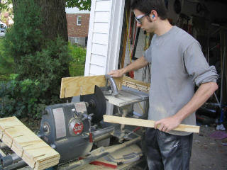
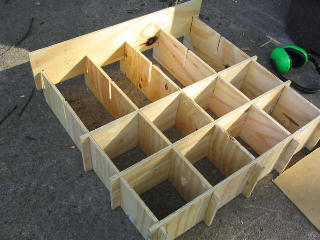
On sunday we went to a shop and assembled two prototype "test modules." each is 2x2 feet, with 16 total pixels. The purpose of these modules is not to test software (they're 1/4 the size of the area controlled by one controller board). These modules were built to test the construction methods and various wood thicknesses for the right balance between strength and weight.
The modules were constructed (and the full floor will be constructed) by cutting notches out of strips of wood and fitting them together. The joints were cut pretty tight to increase structure stability when assembled. Wood glue was then used to further lock the frame together. We built one out of 3/8" plywood, the other out of 1/2". We placed a sheet of 1/4" acrylic on them to test stability when stood and jumped on.
The smaller of the two sizes worked amazingly well even before it was glued which leads us to conclude that we can get away with thinner wood which will decrease costs and weight significantly. We used acrylic for the test because it was all Home Depot carried. It worked well which further assures us that the Polycarbonate (lexan) that we will be using (same thickness) will work even better.
We are using Lexan for the covering because it is stronger and more flexible than acrylic. This will save us if someone with a sharp heel puts a lot of ponit-source pressure on the surface. The floor will (hopefully) flex instead of simply cracking.
Today we ordered the Lexan from Regal Plastics (a St Louis distributor), the rest of the USB-Serial Converters from Parallax, and the powersupplies for the floor from MPJA.
All that is left to buy at this point is the wood for the whole floor, some USB hubs, and miscellaneous supplies.
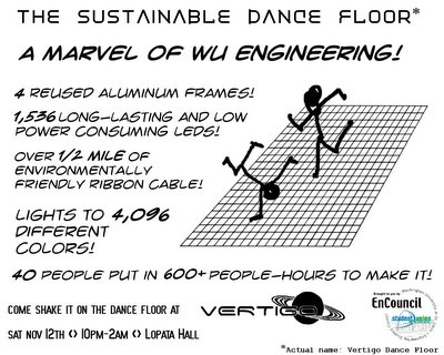
 Wash U IEEE built a large scale light-up computer-controlled dance floor for Vertigo.

